
Introduction
A wind energy conversion system (WECS) is an apparatus that utilizes the kinetic energy of wind and converts it into mechanical or electrical energy. A lot of research has been done to invent an environmentally friendly approach to meet the national energy demand while sustainably utilizing the available resources.
One of the renewable energy sources that is expanding the fastest in the globe is wind energy. Through mechanical and electrical conversion, it makes use of the air masses inherent movement to generate electricity.
Objectives
- To study the working principle of a wind energy conversion system.
- To identify and understand major components involved in the system.
- To evaluate the efficiency and potential of wind energy in electricity generation.
- To explore the advantages, limitations, and future developments in wind technology.
- Designing and constructing a small-scale or large-scale WECS.
- Converting the kinetic energy of wind into mechanical energy via turbine blades, and then converting that mechanical energy into electrical energy using generators.
- Enhancing the efficiency and reliability of the energy conversion process.
- Integrating the system with power electronics, control systems, and energy storage to maximize electricity generation from varying wind speeds.
- Providing a renewable, sustainable, and clean energy source as an alternative to fossil fuels.
- Exploring system components such as charge controllers, inverters, batteries, gearboxes, and power converters to optimize performance.
- Supporting applications such as rural electrification, grid integration, and educational demonstrations.
System Overview / Basic Principle
System Overview
WECS consists of two main types of components:
- Electrical components: generator (converts mechanical energy to electrical energy), power converter (converts DC to AC), step-up transformer (increases voltage), and collection points for delivering electricity from turbines to the grid.
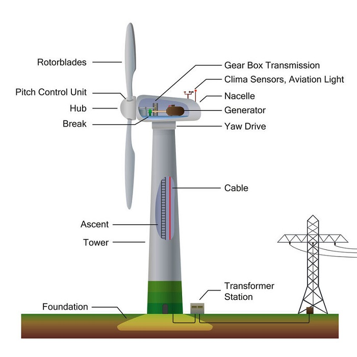
- Mechanical components: rotor (blades attached to a wheel), main shaft, gearbox, mechanical brakes, nacelle (housing for all major components), pitch and yaw drives (to adjust blade angles), and wind measuring equipment (anemometers and wind vanes).
Basic Principle
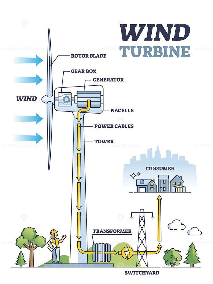
- Kinetic energy of wind rotates the turbine blades.
- The rotor converts kinetic energy into mechanical energy.
- The generator converts mechanical energy into electrical energy.
- The produced electricity is conditioned by power electronics and supplied to the grid or load.
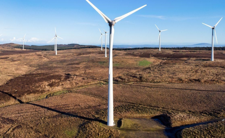
The wind’s kinetic energy turns the rotor blades, causing the rotor to spin. This mechanical rotation transfers through the main shaft to the gearbox, which increases rotational speed suitable for electricity generation. The generator then converts mechanical energy to electrical energy. The electrical output is conditioned and stepped up in voltage for efficient transmission. Multiple wind turbines are often connected in a wind farm to generate commercial levels of power.
Major Components
Mechanical components include:
- Rotor: Comprises blades that capture wind energy and convert it into mechanical rotation.
- Main shaft: Connects the rotor to the gearbox.
- Gearbox: Increases the rotational speed from the rotor for the generator.
- Mechanical brakes: Stop the rotor in high winds or emergencies.
- Nacelle: The housing atop the tower containing the generator and other mechanical/electrical parts.
- Pitch and yaw drives: Adjust blade angle and turbine orientation to optimize wind capture.
- Wind measuring equipment: Anemometers and wind vanes to measure wind speed and direction.
Electrical components include:
- Generator: Converts mechanical energy into electrical energy.
- Power converter: Converts electrical output from DC to AC.
- Step-up transformer: Increases voltage for transmission.
- Wind farm collection points: Collect electricity from multiple turbines.
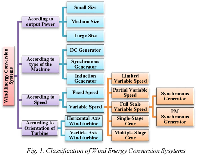
7. Classification of WECS
By Axis Orientation:
- Horizontal Axis Wind Turbine (HAWT)
- Horizontal Axis Wind Turbines (HAWT): Rotor blades mounted on a horizontal shaft perpendicular to the ground. Most commonly used.
- Vertical Axis Wind Turbine (VAWT)
- Rotor blades mounted on a vertical shaft parallel to the ground. Less common, more complex, and less efficient.
By Speed:
- Constant speed systems
- Variable speed systems
- Constant Speed with Variable Pitch Blades
- Nearly Constant Speed with Fixed Pitch Blades
- Variable Speed with Fixed Pitch Blades (including several subtypes with different generator and converter arrangements)
By Size/Power Output:
- Small Power Turbines: Up to around 2-30 kW, used for small-scale needs like home power or battery charging.
- Medium Power Turbines: About 30 to 300 kW, used for small communities or in combination with other energy sources.
- Large Power Turbines: Above 300 kW (sometimes noted as 100 kW and above for large scale), used in large wind farms connected to the grid.
By Electrical Output Type:
- DC Output Systems: Using DC generators or alternator-rectifier setups.
- AC Output Systems: Variable or constant frequency and voltage AC.
By Utilization of Output
- Battery Storage
- Direct Conversion to Electromagnetic Energy Converters
- Thermal Potential
- Interconnection with Conventional Electric Utility Grids
⚙️ Design and Modelling (Expanded Section)
The design and modelling of a Wind Energy Conversion System (WECS) are essential to predict performance, optimize efficiency, and ensure mechanical stability. The process involves aerodynamic, mechanical, and electrical considerations supported by mathematical models and simulation tools.
Aerodynamic Design
The aerodynamic design determines how efficiently the wind turbine extracts kinetic energy from the moving air.
Key parameters include:
- Blade Shape and Length: Longer blades capture more energy but require stronger materials.
- Pitch Angle: Controls the rotation speed and protects the turbine in high wind conditions.
- Tip Speed Ratio (TSR): Ratio between blade tip speed and wind speed; an optimal TSR (usually 6–8 for HAWTs) ensures maximum power.
- Power Coefficient (Cₚ): Represents conversion efficiency; the theoretical limit is 59.3% (Betz Limit).
Mechanical Design
The mechanical structure provides stability and strength to the turbine.
Main components include:
- Rotor Hub: Connects blades and transmits torque.
- Shaft and Bearings: Transfer mechanical power to the gearbox or generator.
- Gearbox Design: Adjusts rotational speed; high-speed shaft drives the generator.
- Brake System: Prevents damage during overspeed or strong winds.
- Tower Structure: Designed based on wind load and vibration analysis for maximum safety.
Electrical Design
The electrical subsystem converts mechanical power into electrical energy and stabilizes output.
- Generator Types:
- Squirrel Cage Induction Generator (SCIG)
- Doubly-Fed Induction Generator (DFIG)
- Permanent Magnet Synchronous Generator (PMSG)
- Power Electronics:
- Rectifiers, inverters, and converters control voltage and frequency.
- MPPT (Maximum Power Point Tracking) ensures maximum output.
- Grid Integration: Electrical design also includes synchronization, reactive power control, and safety relays.
Mathematical Modelling
Mathematical models simulate turbine behavior under different wind conditions.
Basic Power Equation: P=12ρAV3CpP = \frac{1}{2} \rho A V^3 C_pP=21ρAV3Cp
Where:
ρ = Air density (kg/m³)
A = Rotor swept area (m²)
V = Wind speed (m/s)
Cₚ = Power coefficient
Torque Equation: T=PωT = \frac{P}{\omega}T=ωP
Where ω = Angular velocity (rad/s)
These equations are used in MATLAB/Simulink or ANSYS software to analyze system dynamics, predict output power, and optimize design.
Simulation and Modelling Tools
Modern design processes rely on simulation tools for accurate performance prediction.
Common tools include:
- MATLAB/Simulink: Dynamic modelling and control system design.
- ANSYS Fluent / SolidWorks: Aerodynamic flow and structural stress analysis.
- QBlade: Wind turbine blade design and performance estimation.
- HOMER Energy: Hybrid renewable system optimization.
Simulation helps identify ideal parameters for blade angle, rotor diameter, generator type, and tower height for a given wind speed profile.
Prototype Development and Testing
Once the design is finalized, a small-scale prototype is built for testing.
Testing focuses on:
- Start-up wind speed
- Power output at different wind speeds
- Vibration and noise analysis
- Structural safety under gust conditions
Experimental validation confirms that simulation results match real-world performance before large-scale implementation.
Performance Analysis
The efficiency of a wind turbine depends on wind velocity, blade angle, and generator type. Variable speed turbines offer better performance and power stability. The Betz limit (59.3%) defines the theoretical maximum efficiency achievable by any turbine.
- Active and reactive power output under varying wind speeds, where the output power is influenced by the cut-in speed of the turbine and is controlled by components such as pitch angle controllers to limit fluctuations.
- System behavior under fault conditions, such as three-phase faults, which cause a drop in power output and voltage variations. Performance under faults is critical for stability and grid compliance.
- Control strategies such as adaptive control, model reference adaptive systems, and sliding mode control improve the efficiency and dynamic response of the system, aiding in maximizing aerodynamic efficiency and managing grid interactions.
- The use of matrix converters or two-stage matrix converters can optimize power conversion, eliminate bulky DC link capacitors, and improve overall system reliability.
- Experimental data and simulation using tools like MATLAB/SIMULINK are commonly used to validate control methods and system design, focusing on parameters like active/reactive power, voltage stability, torque, and current responses.
Advantages
- Renewable and abundant energy: Wind is a sustainable resource that will not deplete as long as the sun heats the Earth.
- Low operational costs: After installation, WECS systems have relatively low maintenance and operation expenses compared to fossil fuel plants.
- Environmentally friendly: They produce no greenhouse gas emissions or air pollutants, contributing to reduced dependence on fossil fuels.
- Scalability: WECS can be deployed in various scales, from small residential systems to large wind farms.
- Job creation: The wind energy sector supports numerous jobs in manufacturing, installation, maintenance, and services.
- Clean and sustainable power source that helps reduce carbon emissions.
- No fuel cost and stable energy prices since wind is free.
- Quiet operation and no direct environmental pollution.
- Technological advancements have steadily reduced installation costs over time.
Limitations
- The wind has limited speed which lessened the resultant kinetic energy of the wind energy.
- The speed of the wind is not constant. So the inconsistency in speed is not suitable for getting stable energy. It can not be controlled.
- Production of wind energy is a long-term process i.e. it requires a long time to get a significant amount of energy.
- To produce wind energy, we require a large area to make wind farms. Consuming a large place affects the surroundings.
- It also increases the production cost. If wind speed is low we can not get sufficient energy.
- Wind energy depends on change in season or weather. We can not always use wind energy.
Wind energy converts the kinetic energy of wind into mechanical power.The overall impact of wind energy is minor compared to other energies such as solar energy.
Applications
- Telecommunications, radar, and pipeline control systems where remote power is essential.
- Navigational aids and air-traffic control systems requiring reliable power supply.
- Cathodic protection systems and weather stations or seismic monitoring sites.
- Industrial applications, such as hybrid power systems in extreme environments (e.g., Antarctica) that require robust and low-maintenance designs.
- Stand-alone power systems for isolated loads, providing electricity in off-grid or remote areas.
- Distributed generation in wind farms placed onshore, offshore, seashore, or hilly areas for supplying power to the grid.
- Green energy solutions promoting sustainable development and reducing dependence on fossil fuels.
- Power control and energy storage applications, including pumped water storage stations integrated with wind power systems for energy management.
Future Scope
Future research focuses on improving turbine blade materials, smart control systems, and offshore wind farm development. Integration with energy storage and artificial intelligence will enhance performance and reliability.
Conclusion
A key piece of technology for attaining a clean, sustainable energy future is the wind energy conversion system. Wind energy will be crucial in supplying the world’s expanding electricity needs with ongoing innovation and international assistance.