
Traverse surveying is a method in surveying where a series of connected survey lines form a framework, and the lengths and directions of these lines are measured with instruments like theodolites, compasses, chains, or electronic devices. It is used for establishing control networks, property boundary surveys, and various engineering projects.
Types of Traverse
Traverse surveying is a method of surveying in which a series of connected survey lines form a framework, and the directions and lengths of these lines are measured to determine the positions of points on the ground. It is widely used to establish control networks, plot boundaries, and for engineering projects because it provides a structured framework of interconnected lines that can accurately represent an area or route.
- Closed Traverse
- Open Traverse
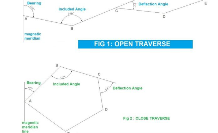
1. Closed Traverse
A closed traverse forms a complete loop, either by returning to the original starting point (loop traverse) or by connecting two known stations (connecting traverse).
A closed traverse is a surveying method where a series of connected measurements forms a complete circuit, either by returning to the original starting point or by connecting two known points.
This method provides a high degree of accuracy and built-in error checking, as the known coordinates at the beginning and end allow surveyors to calculate and distribute any accumulated errors. Closed traverses are fundamental in establishing control networks, property boundary surveys, and various engineering projects where precise spatial relationships are crucial.
Types of Closed Traverse
Loop Traverse:
Starts and ends at the same station, forming a closed circuit.
- Originates and terminates at the same station, completing a circuit.
- Example: As shown in Figure below the traverse starts at station A and follows the route through stations B, C, D, E, and so on, eventually returning to station A.
- The closed circuit formed by the traverse legs is known as the traverse circuit
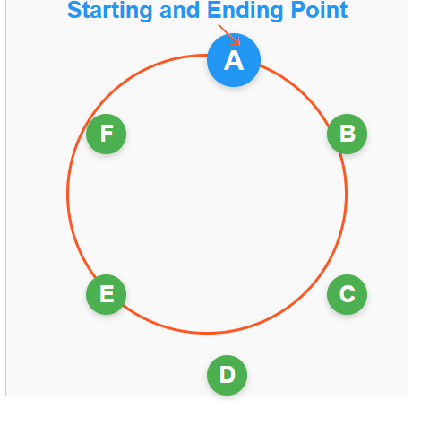 .
.
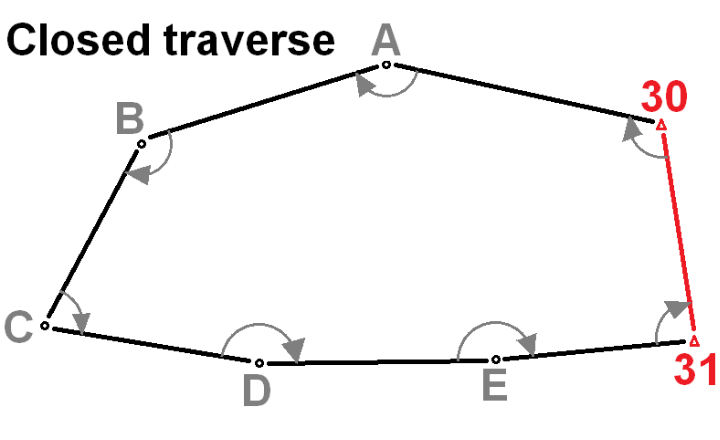
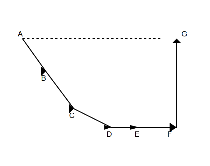
Connecting Traverse:
Begins at one known station and ends at a different known station.
- Begins at one known station and ends at a different known station.
- Example: As illustrated in Figure below, the traverse starts at known station A, passes through stations B, C, D, E, and so on, finally closing on another known station G.
Key advantages of closed traverses:
- High Accuracy: Because a closed traverse forms a complete loop or connects two known points, it allows for the precise determination of positions. The closure enables detection and correction of errors, enhancing overall accuracy.
- Error Detection and Adjustment: The geometric closure of the traverse makes it possible to calculate “closure error,” which can be distributed and adjusted throughout the traverse lines to minimize inaccuracies.
- Redundancy and Reliability: Multiple measurements and the loop structure provide redundancy, helping to verify data and reduce the impact of gross errors or mistakes.
- Suitability for Control Networks: Closed traverses are ideal for establishing control points essential for large-scale mapping, boundary determination, and construction projects, ensuring dependable spatial relationships.
- Efficient for Defined Areas: They are efficient for surveying small to medium-sized enclosed areas, as the survey naturally begins and ends at known stations, facilitating land demarcation.
- Supports Modern Techniques: They can be integrated with modern surveying technologies such as total stations, electronic distance measurement (EDM), and GPS, further improving precision.
Applications of closed traverses:
- Establishing control networks for large-scale mapping projects
- Boundary surveys for property demarcation
- Construction site layouts
- Mining surveys
Measurement techniques:
- Angles are typically measured using a theodolite or total station.
- Distances are measured using electronic distance measurement (EDM) devices, tapes, or chains.
It’s worth noting that modern surveying often employs GPS technology in conjunction with traditional methods to enhance accuracy and efficiency in closed traverse surveys.
2. Open Traverse
An open traverse is a surveying method where the survey line neither returns to its starting point nor closes on a known station. This type of traverse extends in a generally consistent direction through a series of connected lines.
An open traverse is characterized by:
- Starting at a known point but ending at an unknown location
- A series of connected survey lines extending in the same general direction
- Lack of closure on a predetermined point
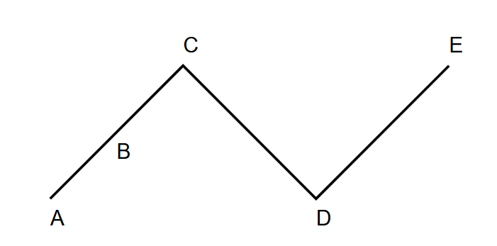
As illustrated in the Figure below, the traverse begins at station A and proceeds through stations B, C, D, and finally terminates at E, where E’s position is not predetermined.
Key characteristics of open traverses:
- No Closure: An open traverse neither returns to its starting point nor connects to any known station, so it does not form a closed geometric figure.
- Starts at a Known Point: The traverse begins from a known location but ends at an unknown point.
- Error Accumulation: Without closing the loop, errors in angle and distance measurements accumulate along the traverse, making error correction difficult.
- Limited Error Checking: Since it lacks closure, there is no natural way to check or adjust for measurement errors, reducing overall accuracy.
- Simplicity and Speed: Open traverses are comparatively easier and faster to execute because they do not require returning to the starting point or another known station.
- Useful for Specific Applications: Suitable for preliminary or exploratory surveys, route surveys like roads, pipelines, railways, and where closure is impractical.
- Measurement Tools: Angles are measured using theodolites or total stations, and distances with electronic distance measurement devices, tapes, or chains. GPS can enhance accuracy in open traverses.
Applications of open traverses:
- Preliminary surveys for road or pipeline routes
- Exploration surveys in remote areas
- River or coastline surveys
- Rapid surveys where time is a critical factor
Measurement techniques:
- Angles are typically measured using a theodolite or total station
- Distances are measured using electronic distance measurement (EDM) devices, tapes, or chains
- GPS technology can be used to enhance accuracy, especially for longer traverses
Advantages of open traverses:
- Speed: Can be faster to execute than closed traverses in certain situations
- Simplicity: Requires less complex calculations compared to closed traverses
- Flexibility: Useful in situations where closing the traverse is impractical or impossible
- Open traverses were more common in early surveying when technology and time constraints often made closing traverses impractical. Modern surveying techniques and equipment have reduced reliance on open traverses for many applications, but they remain useful in specific scenarios.
- In summary, while open traverses have limitations in terms of accuracy and error checking, they remain a valuable tool in the surveyor’s toolkit, particularly for preliminary or exploratory surveys where speed and flexibility are prioritized over absolute precision
Classification of Traverses Based on Instruments Used
Traverses can be classified into several categories based on the surveying instruments employed. Each method offers unique advantages and is suitable for different scenarios. The main classifications are:
- Chain Traversing
- Compass Traversing
- Plane Table Traversing
- Theodolite Traversing
- Tacheometric Traversing
- Electronic Distance Measurement (EDM) Traversing
- Global Navigation Satellite System (GNSS) Traversing
1.Chain Traversing
Chain traversing is a method of traverse surveying where only linear measurements (distances) are taken using a chain or tape, without any direct angular measurements.
Key features:
- Uses only linear measurements
- Angles are computed indirectly from distance measurements
- Suitable for small-scale surveys in open, relatively flat terrain
- Generally less accurate than other methods
In chain traversing:
- No angle-measuring instruments like theodolites or compasses are used.
- The angle between two adjacent traverse lines is found by measuring distances to tie points or by using chords.
- It is primarily used in areas where triangulation is difficult, such as over ponds or in inaccessible terrain, where forming triangles is not possible or practical.
- This method is less accurate compared to compass or theodolite traversing.
Two common ways to fix chain angles are:
- By measuring tie lines between fixed stations on adjacent traverse legs.
- By measuring a chord between traverse lines to calculate the angle using trigonometric relationships.
Chain traversing is simple but suitable only for rough surveys or where approximate measurements are acceptable due to the absence of direct angular control.
Limitations:
- Accuracy decreases for larger angles
- Not suitable for rough or heavily obstructed terrain
- Time-consuming for large surveys
- Doesn’t follow the principle of “working from whole to part
2. Compass Traversing
Compass traversing is a surveying method that involves measuring the directions of survey lines using a magnetic compass, along with linear measurements such as chaining or taping to determine the length of each traverse segment. It combines both angular and linear measurements to establish survey routes over larger or undulating terrains, where high precision triangulation may not be practical.
Key features:
- Uses a magnetic compass for angle measurements
- Distances measured with tape or EDM
- Suitable for moderate-scale surveys
- Affected by local magnetic variations and nearby metal objects
Procedure:
In compass traversing, the traverse angle between two consecutive legs is computed by observing the magnetic bearings of the sides. The process typically involves the following steps:
- Set up the compass at each traverse station.
- Measure the magnetic bearing of each traverse line.
- Measure the distance between stations using a tape or EDM.
- Calculate the included angle between adjacent lines using the difference in bearings.
Advantages:
- Faster than chain traversing
- Provides a reasonable level of accuracy for many applications
- Relatively simple equipment and procedures
- Useful for preliminary surveys and route reconnaissance
Limitations:
- Accuracy is lower than theodolite or total station methods
- Subject to errors due to local magnetic anomalies
- Can be affected by nearby metal objects or electrical currents
- Requires regular calibration and checks for magnetic declination
Applications:
- Topographic surveys of moderate-sized areas
- Boundary surveys of rural properties
- Preliminary surveys for road or pipeline routes
- Geological and forest surveys
Plane Table Traversing
Plane Table Traversing is a surveying method used to plot traverses by moving the plane table sequentially from one station to the next.
Plane table traversing is a unique method of surveying where the map is drawn directly in the field as measurements are taken. In this technique, angular measurements between traverse sides are plotted graphically on a plane table with the help of an alidade.
Key features:
- Combines field measurements and mapping in one step
- Uses a plane table, alidade, and drawing sheet
- Provides an immediate visual representation of the survey
- Suitable for topographic surveys and mapping of moderate-sized areas
Equipment:
- Plane table: A flat surface mounted on a tripod
- Alidade: A sighting device with a straightedge for drawing lines
- Drawing sheet: Mounted on the plane table
- Plumb bob: For centering the table over survey points
- Compass: For orientation
- Measuring tape or stadia rod: For distance measurements
Procedure:
- Set up the plane table at the first station, ensuring it’s level and properly oriented.
- Place the drawing sheet on the table and mark the station point.
- Use the alidade to sight to other stations or objects of interest.
- Draw lines along the alidade’s straightedge to represent sighted directions.
- Measure distances to the sighted points using a tape or stadia methods.
- Scale the distances on the drawn lines to plot the points.
- Move to the next station and repeat the process, using previously plotted points for orientation.
Methods of plane table traversing:
a) Radiation method: Suitable for small areas visible from a single station
b) Intersection method: Uses two known positions to locate new points
c) Resection method: Determines the position of the plane table using known points
d) Traversing method: Used for larger areas, similar to other traversing techniques
Advantages:
- Provides an immediate visual check of the survey’s progress
- Eliminates the need for field notes and office plotting
- Errors can be detected and corrected in the field
- Ideal for filling in details in topographic surveys
Limitations:
- Accuracy is limited by the scale of the drawing and instrument precision
- Weather-dependent (wind, rain can affect the process)
- Difficult to use in heavily forested or built-up areas
- Not suitable for high-precision surveys
Applications:
- Topographic mapping of small to moderate areas
- Updating existing maps with new features
- Preliminary surveys for engineering projects
- Geological and archaeological surveys
Accuracy considerations: The accuracy of plane table traversing depends on several factors:
- Skill of the surveyor
- Precision of the alidade and other instruments
- Scale of the drawing
- Weather conditions
- Careful leveling and orientation of the plane table
Theodolite Traversing
Theodolite traversing is a precise surveying method that uses a theodolite to measure both horizontal and vertical angles at survey stations, combined with linear distance measurements (typically by chaining or taping) between these stations.
Theodolite traversing is a high-precision surveying method in which angular measurements between traverse sides are made with a theodolite. This technique offers significantly improved accuracy over compass and plane table methods, making it suitable for a wide range of professional surveying applications.
Key features:
- Uses a theodolite for precise angle measurements
- Can measure both horizontal and vertical angles
- Distances typically measured with EDM or tapes
- Suitable for high-accuracy surveys and large-scale projects
Equipment:
- Theodolite: A precision instrument for measuring angles
- EDM (Electronic Distance Measurement) device or surveying tape
- Tripod and tribrach for stable instrument setup
- Targets or reflectors for sighting
- Field book for recording measurements
Procedure:
- Set up the theodolite at a traverse station, ensuring it’s level and properly centered.
- Orient the theodolite to a known reference direction (often true or magnetic north).
- Measure the horizontal angle to the next traverse station.
- If required, measure the vertical angle for elevation differences.
- Measure the distance to the next station using EDM or tape.
- Move to the next station and repeat the process.
- Close the traverse by returning to the starting point or a known control point.
Advantages:
- High precision in angle measurements
- Capable of measuring both horizontal and vertical angles
- Suitable for large-scale and high-accuracy surveys
- Forms a strong geometric network when properly executed
Limitations:
- More time-consuming than simpler methods
- Requires skilled operators for best results
- More expensive equipment compared to simpler methods
- Necessitates clear lines of sight between stations
Applications:
- Establishing precise control networks for large projects
- High-accuracy boundary and cadastral surveys
- Engineering surveys for construction and infrastructure projects
- Precise topographic mapping
Accuracy considerations:
The accuracy of theodolite traversing depends on several factors:
- Precision of the theodolite (optical or digital)
- Skill of the operator
- Environmental conditions
- Quality of the distance measurements
Tacheometric traversing
Tacheometric traversing is a surveying method where horizontal and vertical distances are determined by making optical observations with a tacheometer, eliminating the need for direct chaining of distances. This technique allows for rapid data collection of both horizontal positions and elevations, especially useful in rough, hilly, or inaccessible terrains.
Tacheometric traversing is a surveying method in which direct measurements of traverse sides by chaining is dispensed with and these are obtained by making observations with a tacheometer. This technique allows for rapid data collection of both horizontal distances and elevations, making it particularly useful in certain surveying scenarios.
Key features:
- Uses a tacheometer for distance and elevation measurements
- Eliminates the need for direct chaining of distances
- Allows for rapid data collection in varied terrain
- Suitable for surveys in hilly or difficult-to-access areas
Equipment:
- Tacheometer: A specialized theodolite with stadia lines in its reticle
- Stadia rod: A graduated rod for sighting
- Tripod for instrument setup
- Field book for recording measurements
Procedure:
- Set up the tacheometer at a traverse station.
- Sight the stadia rod held vertically at the next traverse point.
- Read the upper, middle, and lower stadia hair readings on the rod.
- Measure the vertical angle to the rod.
- Calculate the horizontal distance and elevation difference using tacheometric formulas.
- Move to the next station and repeat the process.
Tacheometric formulas:
- Horizontal distance = K × (Upper reading – Lower reading) × cos²(vertical angle)
- Vertical distance = K × (Upper reading – Lower reading) × sin(vertical angle) × cos(vertical angle) Where K is the multiplying constant of the tacheometer (usually 100)
Advantages:
- Faster than conventional chaining methods, especially in rough terrain
- Provides both horizontal distances and elevations in one observation
- Useful in areas where direct distance measurement is difficult
- Reduces field time compared to separate distance and leveling operations
Limitations:
- Less accurate than precise EDM measurements
- Accuracy decreases with distance and steep slopes
- Requires clear sight lines between stations
- Affected by atmospheric refraction over long distances
Applications:
- Topographic surveys in hilly or mountainous terrain
- Preliminary surveys for road or railway alignments
- Hydrographic surveys of river cross-sections
- Rapid surveys where moderate accuracy is acceptable
Accuracy considerations: The accuracy of tacheometric traversing depends on:
- Precision of the tacheometer
- Skill of the operator
- Length of sight lines
- Atmospheric conditions
- Verticality of the stadia rod
Global Navigation Satellite System (GNSS) Traversing
Global Navigation Satellite System (GNSS) traversing is a modern surveying method that uses satellite-based positioning systems such as GPS, GLONASS, or Galileo to determine the precise coordinates of traverse stations on or near the Earth’s surface.
Key Characteristics:
- Absolute Positioning: GNSS provides global coordinates based on satellite signals, allowing precise location determination without relying on intervisibility between stations.
- All-Weather Operation: It can function in all weather conditions, day or night, offering versatility over traditional optical methods.
- Non-Line-of-Sight: Unlike total stations or theodolites, GNSS does not require a direct line of sight between survey points, making it effective in obstructed or rough terrain.
- Rapid Data Collection: GNSS receivers can quickly collect coordinate data at multiple stations, accelerating surveying operations.
- High Accuracy: Differential GNSS (DGPS) techniques enhance accuracy, often reaching centimeter-level precision.
- Integration Capability: GNSS can be combined with other surveying methods like total stations for comprehensive control surveys.
Procedure:
- Setup GNSS receivers over traverse stations.
- Collect satellite signals and compute coordinates for each station.
- Use reference stations or base stations for differential corrections.
- Calculate traversing parameters like bearings and distances from coordinate differences.
- Perform error analysis and adjustments similar to traditional traversing.
Applications:
- Large-area control network establishment.
- Topographic and cadastral surveys.
- Route surveys for highways, pipelines, and railways.
- Geodetic surveys and mapping.