
Power factor is an expression of energy efficiency in an electrical system. It is the ratio of the real (or working) power, which is the power used to do useful work (measured in kilowatts, kW), to the apparent power, which is the total power supplied to the circuit (measured in kilovolt-amperes, kVA).
- Formula: Power Factor (PF) = kW / kVA or cos(ɸ), where ɸ is the phase angle between the voltage and current waveforms.
- Range: The power factor is a dimensionless number between 0 and 1 (or 0% and 100%).
Different Methods Used for for Power Factor Correction
The following devices and equipment are used for power factor improvement in an electrical system.
Capacitor Banks:
A bank of capacitors can be installed to reduce the reactive power demand of the load, improving the power factor. The capacitors can be fixed or switched, depending on the load requirements.
- Synchronous Condensers: A synchronous motor operating at no-load and over-excited, can be used as a synchronous condenser to improve the power factor of the system.
- Phase Advancers: Phase advancers are AC exciters connected to the rotor circuit of induction motors to improve the power factor of the motor.

Static Var Compensators (SVCs):
SVCs are solid-state devices that use a thyristor-controlled reactor (TCR) and a thyristor-switched capacitor (TSC) to provide continuous reactive power compensation.
- Active Power Filters: These filters can correct power factor issues by generating current components that cancel out harmonic distortion in the system.
- Switched Capacitor Banks: A switched capacitor bank uses automatic switching devices to vary the reactive power demand based on the load requirements, improving the power factor.
Static Synchronous Compensator (STATCOM):
A STATCOM is a voltage source converter that can provide reactive power compensation, harmonic filtering, and voltage regulation.
- Hybrid Power Filters:Hybrid power filters combine active and passive filtering techniques to provide a comprehensive solution for power factor improvement and harmonic distortion reduction.
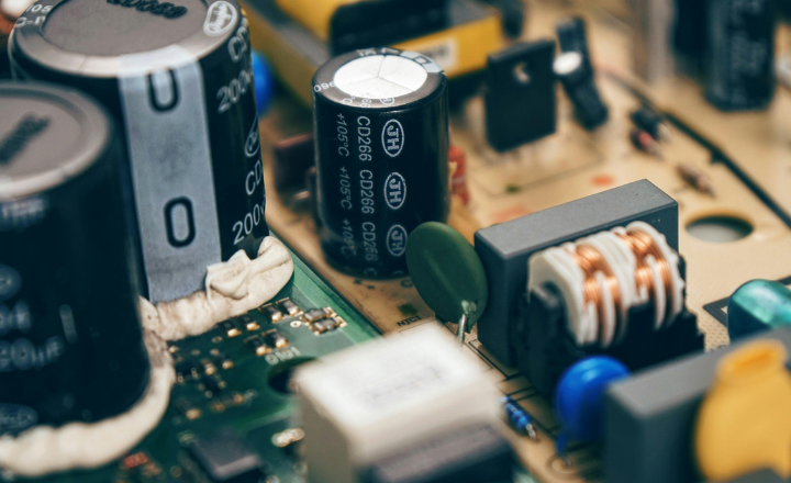
Static Capacitor
A static capacitor is a stationary component used to improve the power factor in electrical systems by providing leading current that neutralizes the lagging reactive current from inductive loads. It is also called a permanent capacitor and is used in some applications, like single-brush sanders, to provide starting torque to motors by creating a phase shift.
Primary uses and benefits
- Power Factor Correction: Static capacitors are connected in parallel with inductive loads to provide the leading reactive power needed to improve the system’s power factor. This can result in lower electricity bills and increased system capacity.
- Starting Torque: In single-phase motors, static capacitors (also called permanent or run capacitors) are used to create a phase shift in the electrical current, which provides the high starting torque the motor needs to overcome inertia.
- Reduced Losses: By improving the power factor, static capacitors reduce overall power losses in transmission and distribution lines.
- Voltage Regulation: They help to improve voltage regulation and reduce voltage flicker in electrical systems.
Advantages:
- Low losses in static capacitors
- No moving parts, therefore requiring low maintenance
- Ability to work in normal conditions (i.e., ordinary atmospheric conditions)
- No requirement for a foundation for installation
- Lightweight, making them easy to install
Disadvantages:
- A shorter lifespan for static capacitor banks (around 8-10 years)
- The need to turn the capacitor bank ON or OFF when there is a change in load, which can cause switching surges in the system.
- Risk of damage if the rated voltage increases beyond its limit
- Expensive repair costs if the capacitors become damaged.
Synchronous Condenser
When a synchronous motor operates at no-load and is over-excited, it is called a synchronous condenser. When a synchronous motor is over-excited, it provides leading current and works like a capacitor.
In a synchronous motor, a separate DC source is used to excite the field winding. Therefore, the input supply only provides current to energize the stator, i.e., the current provided is in-phase with the supply voltage. So the power factor remains unity.
How it works Reactive Power Control:
By varying its field excitation, a synchronous condenser can either supply (over-excited) or absorb (under-excited) reactive power.
- Voltage Regulation: This adjustment of reactive power is used to maintain stable voltage levels across the grid.
- Power Factor Correction: It can correct the power factor of an entire system by counteracting the reactive power needed by loads.
An inductive load consumes reactive power, causing a lagging power factor, while a capacitive load generates reactive power, causing a leading power factor. A synchronous motor can be used to improve the overall power factor of an electrical system by adjusting the DC excitation. The synchronous motor used specifically for power factor improvement without any mechanical load is called a synchronous condenser.
The synchronous condenser is used in parallel with the load to improve the power factor. Improving the power factor reduces the extra current drawn from the source that is wasted in the power lines. Consequently, it helps in the reduction of electricity bills and saves energy.
When a synchronous condenser is connected across the supply voltage (in parallel), it draws leading current and partially eliminates the reactive component. This way, the power factor is improved. Generally, synchronous condensers are used to improve the power factor in large industries.
Advantages:
- Long lifespan (up to 25 years) High reliability
- Allows for stepless adjustment of power factor
- Does not generate harmonics or require maintenance for them
- Faults can be easily removed
- Is not affected by harmonics
- Requires low maintenance (only periodic bearing greasing is necessary)
Disadvantages:
- High cost (including high maintenance costs), therefore it is mostly used by large power users
- An auxiliary device is needed for operation as synchronous motors have no self-starting torque
- Produces noise.
Phase Advancer
The Phase Advancer is a simple AC exciter that connects to the main shaft of a motor and operates with the motor’s rotor circuit to improve power factor. It is commonly used in industries to improve the power factor of induction motors.
Since the stator windings of an induction motor take lagging current 90° out of phase with voltage, the power factor of the motor is low. By supplying exciting ampere-turns from an external AC source, the current does not affect the stator windings, and the power factor of the induction motor improves. This process is done by the Phase Advancer.
How it works
- The problem: Induction motors need a lagging exciting current from the stator to create the magnetic field, which results in a poor power factor.
- The solution: A phase advancer, which is an AC exciter, is connected to the rotor circuit.
- The mechanism: It supplies exciting ampere-turns to the rotor at slip frequency, relieving the stator winding from having to supply this current.
- The result: By controlling the amount of ampere-turns supplied, the motor’s power factor can be significantly improved, potentially making it operate at a leading power factor.
Advantages:
- Sufficiently reduces the lagging kVAR (reactive component of power or reactive power) drawn by the motor because the exciting ampere turns are supplied at slip frequency (fs).
- The Phase Advancer can be easily used where the use of synchronous motors is unacceptable.
Disadvantage:
Using a Phase Advancer is not economical for motors below 200 H.P. (about 150kW).
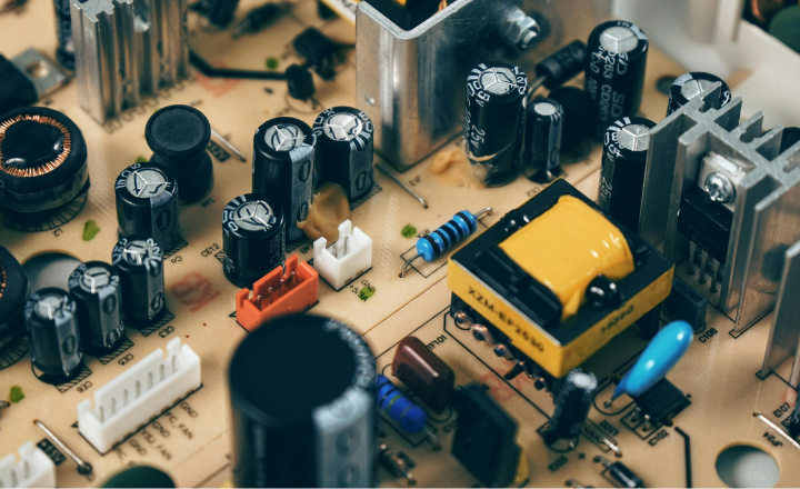
Capacitor Banks
The capacitor bank (published as separate & descriptive article) is connected in parallel to the load, and when the inductive load draws current from the system, the capacitor bank supplies capacitive reactive power to offset the inductive reactive power. The amount of capacitive reactive power needed to improve the power factor depends on the characteristics of the load, such as the magnitude of the inductance and the phase angle between the voltage and current.
Primary functions and benefits Power factor correction:
- Power factor correction: They improve the power factor by compensating for reactive power, which minimizes energy loss and improves the quality of the power supply.
- Voltage support: They help regulate voltage levels, especially in areas with fluctuating loads, by providing local reactive support.
- Energy storage: They store excess energy generated during peak production and release it during peak demand, optimizing distribution.
- Flexibility: Capacitor banks can be made of modular, smaller units that can be switched on or off in stages to provide more accurate control and flexibility.
Types of capacitor banks
- Fixed banks: The simplest type, cost-effective, and best for stable, consistent loads.
- Automatic banks: Use automated control systems to adjust to varying loads, making them suitable for industrial applications.
- Switched banks: Can be manually or timer-controlled, suitable for moderate load variations.
- Tuned/Detuned banks: Specifically designed to filter harmonics or to avoid resonance with harmonics. Tuned banks are ideal for filtering specific frequencies, while detuned banks prevent resonance issues.
- Hybrid banks: A combination of different types to handle complex systems with high harmonic content.
Static VAR Compensator (SVC)
We have covered this topic in a separate article describing Static VAR Compensator (SVC) including a circuit diagram, construction , working principles, and applications. You can read the article to learn how SVCs are used for power factor improvement
How it works
- Voltage stabilization: The SVC continuously monitors the system voltage. When the voltage drops, it injects capacitive reactive power into the system. When the voltage rises, it absorbs reactive power by switching to an inductive mode.
- Thyristor-Controlled Reactors (TCRs): These absorb reactive power from the grid. The amount of absorption is controlled by varying the firing angle of the thyristors, which is done using a real-time digital simulator and a physical hardware model, as described by IEEE Xplore.
- Thyristor-Switched Capacitors (TSCs): These inject capacitive reactive power into the system. The amount is controlled by switching banks of capacitors in and out of the circuit.
- Rapid response: SVCs are designed for fast-acting response times, often within milliseconds, making them highly effective for stabilizing grids that experience rapid voltage fluctuations.
Conclusion
Improving power factor is essential to reduce system losses and improve electrical efficiency. Different methods like capacitors, synchronous condensers, APFC panels, and VSDs provide effective solutions depending on the application. While each method has its advantages, it also has limitations in terms of cost, complexity, and suitability. Choosing the right technique ensures reliable, energy-efficient, and economical operation.