
Objective
- The project objective for designing and implementing an Overload Protection System (OPS) is to develop a system that monitors electric current to detect overload conditions and automatically disconnects the power supply to prevent damage to electrical appliances or circuits.
- The system aims to provide precise current measurement, rapid overload detection, and reliable protection against electrical hazards such as overheating, fires, and equipment damage. It often involves components such as current sensors, microcontrollers for data processing, and relays to cut off power when the current exceeds safe thresholds. The design seeks to optimize energy use, improve safety, and ensure system compatibility and cost-effectiveness.
- This project’s primary goal is to prevent damage to electrical circuits and appliances from overload or excessive current flow by automatically cutting off the power supply when the load beyond a certain threshold.
Introduction
Overload prevention is crucial in contemporary electrical systems to avoid short circuits, equipment damage, and fires brought on by high current.
A straightforward and automated Overload Protection System that tracks the current drawn by a connected load is presented in this project.
The system uses a relay or circuit breaker mechanism to automatically switch off the power supply when the current beyond a certain safe level.
It guarantees dependability, safety, and energy efficiency, particularly in residences, businesses, and labs.
Working Principle
- Current Sensing: The system continuously measures the current drawn by devices or loads using sensors or monitoring elements.
- Threshold Setting: A maximum allowable current limit is predefined based on the capacity of the circuit or equipment.
- Response Mechanism: When the current exceeds this limit, the overload protection device reacts by disconnecting the circuit or shutting down some loads to prevent damage and overheating.
- Thermal and Magnetic Components: Common OPS devices include thermal elements like bimetallic strips that bend when heated by excess current, or magnetic coils that trip circuit breakers.
- Control and Display: In intelligent OPS designs, software can prioritize device operations, turning off less critical loads to keep total current within limits, with real-time status shown on displays.
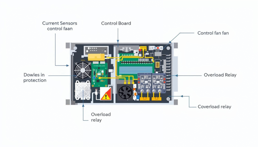
Components required
The components required for designing and implementing an Overload Protection System (OPS) typically include:
- Current Sensing Element: A current transformer or sensor to measure the current flowing through the system.
- Overload Detection Circuit: To compare the measured current with a preset threshold to detect overload conditions.
- Timer Circuit: To provide delay time before tripping to avoid nuisance tripping on transient conditions.
- Trip Mechanism: A relay or contactor that disconnects the load when overload is detected.
- Indicator Lamps or Display: To show the status of the system such as overload condition or normal operation.
- Adjustable Settings: Controls to set the maximum allowable current for protection operation.
- Control Circuit: To manage the operation logic, start/stop conditions, and resetting the system.
- Auxiliary Components: Such as fuses, switches (manual contactor or HOA – Hand-Off-Auto switch), and wiring.
This set of components forms the basis for a typical Overload Protection System used for motors, transformers, and various electrical appliances.
Block diagram (description)
The block diagram of an Overload Protection System (OPS) generally includes the following main components:
- Current Transformer (CT): Detects the current flowing through the circuit. It steps down the current to a lower, measurable value proportional to the actual current.
- Overload Detector: Uses the output from the current transformer to detect overload conditions by comparing the measured current against a preset threshold.
- Comparator Circuit: Compares the overload detector signal with a reference level. If the current exceeds the reference, it triggers the next stage.
- Timer (Trip Timer): Once an overload is detected, the timer circuit (often a monostable multivibrator with IC 555) is triggered. It controls how long the load remains disconnected before attempting to reset.
- Trip Counter: Counts the number of times the overload condition causes a trip. This helps manage automatic retries or permanent disconnection after repeated faults.
- Output Control Switch and Relay: Controls the disconnection of the load from the power supply, based on the timer and trip counter signals.
- Display/Indicators: LEDs or other visual indicators show the system status like normal operation, overload warning, or trip condition.
- Reset Mechanism: Allows manual or automatic resetting of the system after the fault condition is cleared.
The trip counter tracks repeated trips, and after a preset number, a permanent disconnection occurs until manual reset. This protects the system from sustained overloads or faults.
This block diagram setup can be adapted for single or three-phase systems and includes protection against both overload and short-circuit conditions. It ensures automatic trip management with retry attempts and status indication for maintenance and safety.
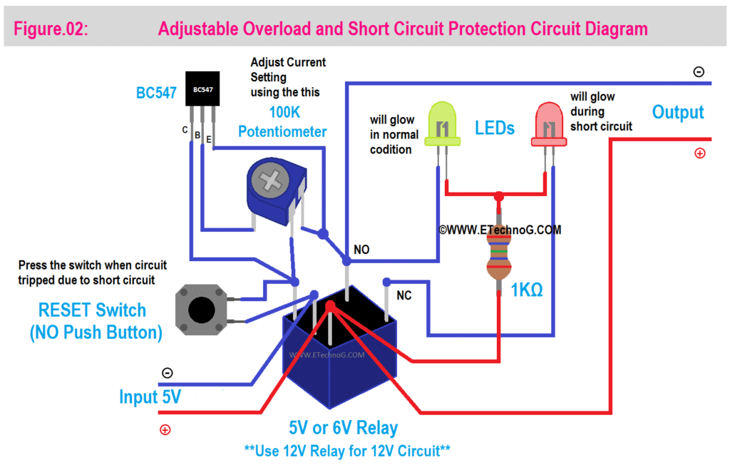
Circuit explanation
The automatic overload protection system (OPS) circuit generally consists of several essential components, including a current sensing unit, comparator, timer, counter, and output control switch. The core idea is to detect over current conditions such as overload or short circuit in a power line and then automatically disconnect the load to prevent damage.
Circuit Explanation of OPS:
- Current Sensing Unit:
- A current transformer (CT) monitors the current flowing through the power line.
- The CT outputs a voltage proportional to the primary current.
- This output voltage is then rectified and filtered using a diode and capacitor to provide a DC voltage.
- Comparator (Using IC LM324):
- The filtered voltage is fed to a comparator.
- The comparator compares this voltage with a preset reference voltage level.
- If the detected current exceeds the reference (indicating an overload), the comparator output switches states (usually goes low).
- Trip Timer (Using IC 555 Monostable Multivibrator):
- The comparator output triggers the timer.
- The timer provides a time delay window during which the load is disconnected.
- The duration of this “trip” is set by the RC time constant of the IC 555 circuit.
- The timer output goes high during this period and returns low after the set time.
- Trip Counter (Using CD4017 Decade Counter IC):
- Each trip event increments the counter.
- The counter helps keep track of how many times the load has been disconnected due to overload.
- LEDs connected to the counter outputs visually indicate the trip count and system status.
- Output Control Switch:
- The output of the timer and counter controls a switch (could be a relay or semiconductor switch) to disconnect the load.
- The switch will break the circuit to the load during overload conditions.
- After the timer elapses, the system tries to reconnect the load.
- If overload persists, the cycle repeats up to a preset number of times.
- After reaching the maximum reset attempts, the system permanently disconnects the load until manually reset.
Functionality Overview:
- The system continuously senses line current.
- When overload or short circuit occurs, the current sensor sends a signal.
- The comparator detects the overload condition and triggers the trip timer.
- The timer controls load disconnection for a safe period.
- The trip counter tracks and limits the number of retries.
- If faults persist, the system disables the load permanently until intervention.
This design ensures automatic protection against damage due to excessive currents by timely disconnecting and attempting resets, with indication via LEDs and a logic circuit controlling the load switch.
Applications of Overload Protection System (OPS)
An Overload Protection System (OPS) is critical for safeguarding electrical equipment, particularly motors and transformers, from damage caused by excessive current and overheating. The applications of OPS span multiple industries and sectors, where its implementation ensures operational continuity, safety, and equipment longevity.
- Manufacturing Plants: Protects motors driving conveyor belts, pumps, compressors, and other machinery, preventing operational disruptions due to motor failures caused by electrical faults or overheating.
- Energy Sector: Safeguards turbines, generators, and associated power generation equipment from overload situations, enhancing the reliability and safety of power systems.
- Building Automation: Widely used in HVAC systems, elevators, and other building electrical installations to prevent motor failures and enhance system safety in residential, commercial, and industrial buildings.
- Agricultural Equipment: Maintains safe operation of irrigation pumps, grain conveyors, and other agricultural motors that operate under variable load conditions, critical for rural and farming operations
- Mining Industry: Protects motors powering conveyor belts, rock crushers, and pumps in harsh mining environments, reducing costly downtime from motor overload.
- Water and Wastewater Management: Ensures pumps and filtration equipment run reliably by preventing overheating and overload, critical for continuous water treatment and distribution.
- Transportation and Logistics: Applied in electric railways, escalators, automated sorting machines, and conveyor systems to protect motors from overload and ensure smooth transportation operations.
- Smart Homes and Automation: Modern OPS designs control and prioritize multiple devices based on current limits, preventing overload scenarios by monitoring individual device currents and managing load distribution intelligently.
- Industrial Automation: Smart overload relays offer real-time monitoring and predictive maintenance capabilities, integrating into automation systems to optimize performance and reduce equipment failure risks.
Advantages
- Equipment Safety and Longevity: OPS helps prevent damage to electrical equipment by detecting and interrupting overload conditions promptly, thus extending the machinery’s lifespan by avoiding overheating and stress beyond capacity.
- Real-Time Monitoring and Precision: Modern OPS can use current sensors that offer real-time and more accurate overload detection compared to traditional fuses or circuit breakers, allowing faster and more precise protection actions.
- Reduced Maintenance and Downtime: OPS based on sensors or relays do not require replacement after one overload event, unlike fuses, and can reduce system downtime and maintenance costs by providing continuous protection.
- Customization and Integration: OPS can be tailored for specific operational conditions with adjustable thresholds and can integrate with smart systems for remote monitoring, predictive maintenance, and energy management.
- Enhanced Safety for Workers: By preventing equipment overloads, OPS also protects operators and employees from electrical hazards and potential accidents caused by equipment failure.
- Automation and Efficiency: OPS automates the overload protection process, minimizing manual intervention, saving time, and avoiding complete system outages, especially useful in complex environments.
Conclusion
Designing and implementing an Overload Protection System (OPS) involves creating a mechanism that monitors and controls the electrical load to prevent damage caused by excess current.
The system typically includes current sensors to detect the current drawn by devices, a control unit to analyze the data, and a method to disconnect or manage the loads when the current exceeds a preset safe limit.
The system may include features like status indication, automatic reset after fault clearance, and user interfaces for setting current limits and monitoring status. Successfully deploying such a system improves safety, prevents equipment damage, and ensures reliable power distribution by dynamically controlling loads according to their priority and current usage