
Components of theodolite is an instrument designed for the precise measurement of horizontal and vertical angles. It was initially developed in 1690 by Ole Roemer, a Danish astronomer, to observe the passage (or transit) of stars across different segments of the celestial meridian. Around a century later, the theodolite underwent modifications to meet surveying requirements, enabling it to measure both horizontal and vertical angles more effectively. By 1830, additional enhancements further expanded its range of applications, allowing it to measure a variety of parameters beyond simple angles.
Because of its versatile functionality, a theodolite is often regarded as a universal instrument. It is employed in various tasks, such as measuring horizontal and vertical angles, extending straight lines, determining bearings, calculating horizontal and vertical distances, and establishing the direction of true north. Although the exact origin of the term “theodolite” remains unclear, it is distinguished from a transit instrument primarily by its longer size and its ability to read smaller angular values, even to 1 second of arc, making it more precise than a standard transit.
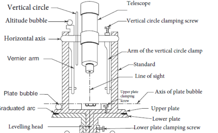
Levelling Head
The leveling head consists of two parallel horizontal plates separated by three leveling screws. The lower plate, called the trivet or foot plate, attaches to the tripod and has a central hole for suspending a plumb bob. The upper plate, called the tribrach, carries the instrument and has three leveling screws that allow precise adjustment for leveling the instrument horizontally. The three screws work together by adjusting two screws simultaneously to level in one axis and the third screw to level in the perpendicular axis, following the left thumb rule for fine calibration. This mechanism ensures the instrument is stable and accurately leveled for precise measurements
The leveling head is designed to perform three primary functions:
- Supporting the main parts of the theodolite.
- Attaching the theodolite securely to the tripod.
- Leveling the instrument accurately to ensure precise observations.
It is divided into two main parts:
The lower tribrach has a circular hole at its center. This opening allows for a plumb bob to be suspended through it, enabling the quick and accurate centering of the instrument over a specific ground station point. Proper centering is crucial for maintaining the accuracy of angular measurements during surveying operations.
Upper Tribrach
The upper tribrach is constructed with three arms, each carrying a levelling screw. These levelling screws are essential for both supporting and leveling the theodolite.
At the center of the upper tribrach, there is a female axis, which accommodates the lower male vertical axis of the theodolite, allowing for smooth and precise movement.
Lower Tribrach
The lower tribrach has a circular hole at its center. This opening allows for a plumb bob to be suspended through it, enabling the quick and accurate centering of the instrument over a specific ground station point. Proper centering is crucial for maintaining the accuracy of angular measurements during surveying operations.
The lower plate or (Scale plate)
The lower plate of the levelling head, also known as the trivet or foot plate, is a horizontal circular plate with a large threaded hole in its center. It is used to securely attach the instrument to the tripod stand by screwing it onto the tripod’s male screws. The central aperture of the lower plate allows for the suspension of a plumb bob, which helps in centering the instrument precisely over a survey point. The lower plate provides a stable base for the instrument and works in conjunction with the upper plate (tribrach) and leveling screws to ensure accurate leveling of the instrument.
- The Lower Plate, also referred to as the Scale Plate, is a crucial component of a transit theodolite, attached to the outer spindle and featuring a horizontal graduated circle along its beveled edge. This circle is graduated from 0° to 360°, with each degree further subdivided into ten-minute or twenty-minute arc intervals, allowing for precise angular measurements. The lower plate can be clamped in any desired position using a clamping screw, while a corresponding tangential (slow motion) screw enables fine adjustments, allowing for subtle corrections without altering the entire plate’s position.
- When the lower clamp is tightened, the lower plate is securely fixed to the upper tribrach of the leveling head, ensuring the stability of the instrument during observations. The size of the theodolite is defined by the diameter of the lower plate, which typically ranges from 8 cm to 25 cm. For instance, a 13 cm theodolite signifies that the diameter of its lower plate measures 13 cm, directly impacting the instrument’s precision and readability. Thus, the lower plate, with its fine graduations and precision adjustments, serves as a foundational component, enabling accurate horizontal measurements and providing a stable base for precise angular observations.
The Upper Plate (or Vernier Plate)
The Upper Plate, also known as the Vernier Plate, is attached to the inner spindle axis of the theodolite and supports the telescope standards on its upper surface. The upper plate includes an upper clamp screw and a tangent screw that allow it to be clamped to the lower plate or rotated independently for fine adjustment and accurate angle measurement.
- The Upper Plate, also known as the Vernier Plate, is attached to the inner spindle axis of the theodolite. This plate is equipped with two verniers positioned diametrically opposite to each other, allowing for precise angular measurements. The upper plate is designed to overlap and protect the lower plate, fully covering the horizontal circle, except at the areas directly below the verniers, which are exposed for reading. To enhance visibility, the verniers are fitted with magnifiers, ensuring the accurate reading of smaller angular values.
- Conversely, if the lower clamp screw is engaged and the upper clamp is released, the instrument rotates about its inner spindle, resulting in relative motion between the vernier and the graduated scale of the lower plate. This mechanism is crucial for measuring angles between two distinct settings of the instrument. It is essential to ensure that the clamping screws are properly tightened before utilizing the tangent screws for fine adjustments, as this prevents any unintended motion, allowing for precise alignment and measurement.
The Standards (or A Frame)
The leveling head uses three screws to adjust and level the instrument horizontally. By turning two screws simultaneously, the plate is leveled in one direction, and the third screw adjusts it in the perpendicular direction for precise leveling.
- The Standards, also known as the A Frame, are a pair of rigid structures shaped like the English letter “A” and are firmly attached to the upper plate of the theodolite. These standards serve as bearings for the pivots of the telescope, providing crucial support and stability. The tops of the standards form the bearing surfaces, allowing the telescope to rotate freely around its horizontal axis in the vertical plane, enabling precise elevation and depression measurements.
- The standards are designed to be sufficiently high to accommodate the full vertical rotation of the telescope without obstruction. Additionally, the T-frame and the arm of the vertical circle clamp are also securely attached to the standards, contributing to the structural integrity and operational functionality of the instrument. By providing a stable support system, the standards ensure that the telescope movements are smooth, allowing for accurate vertical and horizontal observations.
T-Frame or Index Bar
The T-Frame, also called the Index Bar or Vernier Frame, is a T-shaped structure centered on the horizontal axis of the telescope within the vertical circle frame. It has two arms: a vertical arm that helps lock the telescope at the desired angle, and a horizontal arm known as the Index Arm, which carries verniers used for measuring vertical angles on the vertical circle. The vertical leg of the T-frame, also called the Clipping Arm, has clamping screws and a fork to secure the frame. Additionally, a bubble tube is mounted on the T-frame for accurate leveling in the vertical plane, ensuring precise vertical angle measurements during surveying.
- The T-Frame, also referred to as the Index Bar, is a T-shaped structure centered on the horizontal axis of the telescope within the frame of the vertical circle. The horizontal arm of this T-frame, known as the Index Arm, holds two verniers—C and D—positioned at its ends, which are used for reading vertical angles on the vertical circle.
- The vertical leg of the T-frame is termed the Clipping Arm. It is equipped with a fork and two clamping screws at its lower extremity, providing secure attachment and stability. The index and clipping arms together form what is collectively known as the T-Frame.
- At the top of the T-frame, a bubble tube is affixed, known as the Altitude Bubble Tube. This bubble tube is used for accurately leveling the instrument in the vertical plane, ensuring that all vertical measurements are taken from a properly leveled position. The T-frame’s precise construction and the placement of verniers and leveling aids make it essential for achieving accurate vertical observations during surveying tasks.
Plate Levels
Plate levels are precision spirit or bubble levels mounted on the plates of surveying instruments like theodolites or total stations. The plate levels typically consist of small tubular vials filled with liquid and an air bubble, aligned at right angles to each other for leveling in two perpendicular directions simultaneously.
- The Plate Levels are precision components mounted on the upper plate of a theodolite to assist in leveling the instrument. Typically, there are two plate levels positioned at right angles to each other. One of these plate bubbles is aligned parallel to the trunnion axis, ensuring accurate leveling in one direction.
- The plate levels are centered using the foot screws, which provide fine adjustments to achieve a perfectly leveled position. Proper leveling is crucial for ensuring that horizontal and vertical angle measurements are accurate and reliable. In some theodolite models, only a single plate level is provided, which is still sufficient for achieving the necessary leveling precision in most surveying applications.
Telescope
The telescope in surveying instruments is a sighting device used to locate and view the target or object being measured visually. It typically consists of an objective lens that gathers light, an internal focusing system including a movable double concave lens for sharp images, and a diaphragm with cross-hairs for precise alignment. The telescope is mounted on the standards (A-frame) and rotates around a horizontal axis for vertical angle measurements. It has optical lenses and sometimes prismatic systems that help in magnification and focusing, allowing surveyors to make accurate angular measurements of distant points by aligning the cross-hairs with the target
External Focussing Telescope
An External Focussing Telescope consists of two main tubes: the outer tube and the inner tube. The outer tube is fixed to the pivot using a sturdy metal band, while the inner tube slides within the outer tube using a rack and pinion mechanism. This mechanism is operated by turning a large milled-head screw, allowing the telescope to be focused on varying distances. Typically, the object glass is mounted at the end of the inner tube. While this type provides straightforward focusing, it can alter the overall length of the telescope, potentially affecting the instrument’s balance.
Internal Focusing Telescope
The Internal Focusing Telescope employs a different design. It features an internal focussing lens, usually a double concave lens, positioned between the objective and the eyepiece, both of which are fixed at the ends of the main tube. Focusing is achieved by moving the internal focusing lens with a focusing screw. This design does not alter the overall length of the telescope during focusing, ensuring stability and balance.
Advantages of an Internal Focusing Telescope:
- The overall length of the telescope remains unchanged during focusing, which maintains the balance of the instrument.
- There is no risk of damaging the parallel plate bubble or compass glass cover underneath while transiting the telescope.
- The wear on the rack and pinion mechanism is reduced due to minimal movement of the internal lens.
- The line of collimation is minimally affected by focusing, ensuring higher accuracy.
- The telescope remains free from dust and moisture, enhancing durability and reliability.
- During tacheometric observations, the additive constant is generally eliminated, simplifying computations.
- The combined focal length of the internal lenses increases the telescope’s power, improving magnification.
- By incorporating a concave lens, the diameter of the objective can be increased without introducing aberrative effects, resulting in clearer and sharper images.
Thus, the internal focusing telescope is considered superior for most precision surveying tasks, offering enhanced stability, durability, and ease of use compared to the external focusing type.
Vertical Circle
The Vertical Circle is a crucial component of a theodolite, attached directly to the telescope and used to measure elevations and depressions. It is graduated in several different ways depending on the manufacturer. This allows for various methods of reading vertical angles in different configurations. The following are the three common graduation styles of the vertical circle:
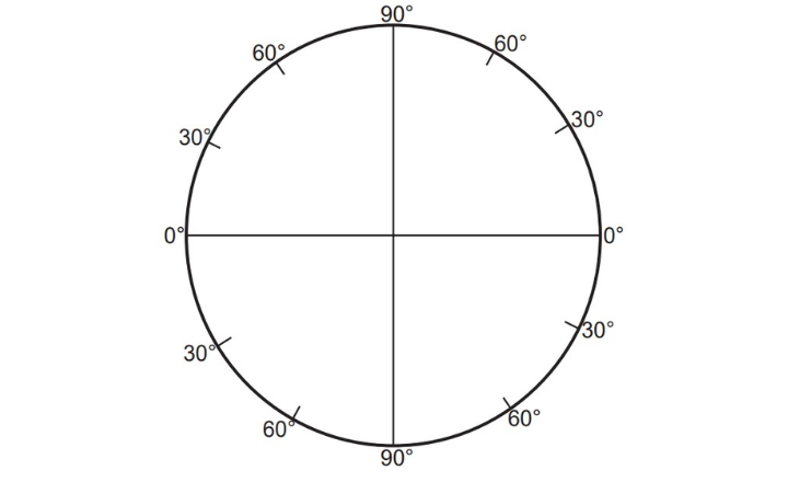
Four-Quadrant Graduation: 0° to 90°
In this configuration, the vertical circle is divided into four quadrants, each reading from 0° to 90° in the same direction. The setup allows for easy measurement of elevations on one face of the theodolite and depressions on the other face. This makes it straightforward to switch between readings based on the telescope’s orientation.
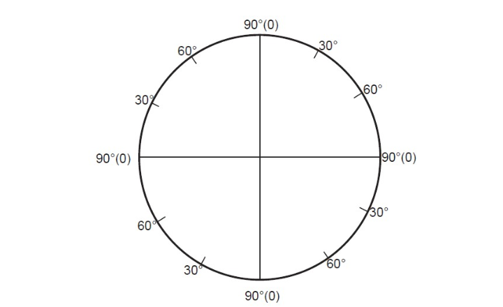
Four-Quadrant Graduation: 0° to 90° in Both Directions
In this style, the vertical circle is again divided into four quadrants, but the 0° mark is placed at the eyepiece end and the objective end, extending to 90° in both directions. The result is that elevations and depressions can be read symmetrically on both faces of the theodolite, making it versatile for readings without needing to switch face orientations.
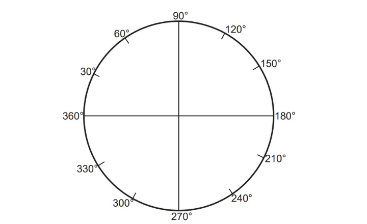
Full-Circle Graduation: 0° to 360°
In the full-circle configuration, the vertical circle is graduated from 0° to 360°. In this type, the zero point can be set at any position, allowing flexibility in taking measurements. To determine the true elevation or depression using this graduation style, the following rules are applied:
- If the difference between the greater and lesser readings is greater than 180°, the angle represents an elevation. To obtain the true elevation, subtract this value from 180° and divide by 2.
- If the difference is less than 180°, the angle indicates a depression. To determine the true depression, subtract this value from 180° and divide by 2.
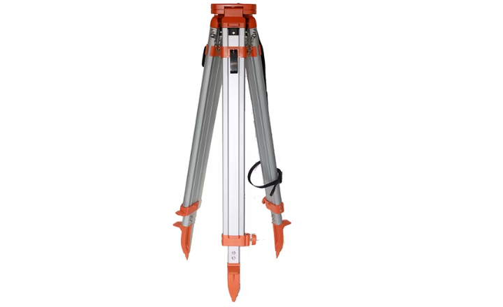
Tripod
A tripod in surveying is a three-legged stand that provides a stable and level platform for supporting surveying instruments such as theodolites, total stations, laser levels, and GNSS receivers. It helps maintain the instrument’s position firmly and accurately on various terrains, allowing precise measurements by preventing movement or vibration. Tripods generally have adjustable telescoping legs to accommodate uneven surfaces and come with either flat or dome heads to securely mount different types of instruments. Their stability and ability to keep instruments level and centered over survey points are crucial for reliable and repeatable survey results.
The Tripod serves as the foundational support structure for the theodolite during fieldwork, ensuring stability and accuracy of the instrument. It typically consists of three solid or framed legs, which provide a firm base for the theodolite, allowing for reliable observations. Each leg is equipped with pointed iron shoes at the lower ends, enabling them to be securely anchored into the ground, preventing any slippage or movement.
- The tripod head is an essential part of the tripod assembly. It features an external screw on its upper surface, which is used to securely attach the foot plate of the levelling head. This connection ensures that the theodolite remains stable and accurately positioned during surveying operations. By maintaining the theodolite in a steady and level position, the tripod minimizes vibrations and disturbances, which is critical for precise angle measurements and readings.
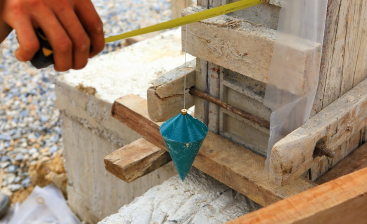
Plumb Bob
A plumb bob is a pointed weight, typically made of metal like brass or steel, suspended from the end of a string. It is used to establish a vertical reference line, known as “plumb,” by allowing gravity to pull the weight straight down.
- The Plumb Bob is a simple yet crucial component of a theodolite, used for precise centering of the instrument over a ground station mark. It consists of a weighted, pointed metal object suspended from a hook attached to the bottom of the main vertical axis. By aligning the plumb bob’s point directly above the station mark, surveyors can ensure that the theodolite is positioned accurately over the exact reference point, maintaining the vertical alignment of the instrument.
conclusions
The theodolite is an advanced device made up of several essential components that cooperate to provide accurate angular readings. Professionals can maximize the device’s performance by being familiar with every part, from the leveling screws to the vertical circle. Gaining proficiency in these areas can greatly increase accuracy and decrease mistakes made when conducting surveys. Any aspiring surveyor must stay up-to-date on these crucial components as the field evolves with new technologies.